Saturday, February 28, 2015

Assembling the Drive Unit

Over the last few weeks, and particularly this week of school vacation, I've put a lot of time into the bike and it's all coming together. What I'm calling the drive unit, the aluminum box to which the motor, jackshaft, pulleys, and controller mount to, is almost done. The assembly process is more complicated than I ever imagined, because each component blocks another from being installed, and so it took me a while to figure out the order to install them in. Although the CAD software helped me make sure everything actually fits, there is very little room inside for your hands to, say, tighten a screw. Tonight I needed to enlarge two of the holes with the drill press, and in order to have the drive unit sit flat, I had to almost completely disassemble it. An assembly guide like this is a good way to convey all the details that went into this design and construction, with the added benefit of being a reference for me and anyone who builds a bike based on mine to look back on. First, the end product.


To assemble the unit, you have to start with screwing the precharge button and the master switch onto the front of the box. They connect to each other with a JST-SM connector, which I use for all my signal connections, and are great except for the fact that they're not waterproof. The LED in the button is connected across the precharge resistor, so that it lights up in proportion to the current going through the power resistor. That is, it would light up when you first press it, and then fade as the controller's capacitor charges, except that I made the assumption that the button had a resistor built in for the LED, which it does not, and so it's burned out now.

Next come the bearings, which are mounted with #4 screws, instead of the #6 they were made for, to allow them to be aligned and make up for my inaccurate machining work.

After that, you install the intake fan, which blocks the switch from being removed. First you install the grill onto the output side of the fan, which keeps wires from getting in the blades, and then bolt the fan into the enclosure, with a filter to keep the dust and mud out.

The shaft goes through one bearing, you slip on the thrust bearings and shaft collars, and then you push it through the other bearing. I plan on adding wave washers to the sandwich to reduce the vibration of the thrust bearings. The shaft blocks some of the nuts on the fan, making that a pain to install or remove without removing the shaft. This is as far as I disassembled tonight, and so I should have pictures from here on down.


The negative wire gets routed between the fan and the enclosure wall, and then a piece of solid 22AWG wire is pulled through two holes in the aluminum and around the wires, keeping them in place and from touching the spinning outside of the motor. I just switched to the silicone jacketed wire from Hobbyking, and it's amazing. Extremely flexible due to it's hundreds of tiny strands, each of which is nickel plated to prevent corrosion, and the insulation is thick, similarly flexible, and rated for high temperatures. Seriously, I'm never going back to the terrible hardware store stuff again. It was surprisingly difficult to get the solder to flow through all the little strands, but the crimps came out strong.


After routing the wires, the first half of the HDPE clamps get attached, because the screws can't be inserted once the motor is in place.


Next, the motor. Can we take a moment to enjoy those beautiful copper windings?


It gets secured with a few Allen screws, which need to get replaced with flat heads and countersinked. I can't find my countersink bit, I think I have to get a new one. They're just so useful.


The brackets for the controller get attached with 4 #6 screws tapped into the box. Yes, I know the screws don't match, I didn't have enough pan heads.
Then the controller, which unfortunately covers the holes for the brackets, so removing the brackets is a two step process involving screws into the controller whose threads are barely holding. Aligning the brackets is even more of a pain.
I don't have a picture of the before, but the controller has very few of its original wires left on it. I opened it up and cut off all the wires I don't need at the circuit board, cut the power on and mode selection wires to an inch long and soldered them within the case, and replaced all the connectors on the wires I want with, from top to bottom, XT90 for the battery, 4mm gold plated bullet connectors for the motor, and JST-SM again for the throttle. The Hall Effect Sensor wires, which I don't need now but might later, were stripped of their connector, heat shrinked, and taped to the controller.

To protect the electronics from road spray, I used a 4" fence post cap to cover the bottom, with a hole in it for the wires to pass through.  I have to drill some more holes in this cap, to act as exhaust for the fan in order to route the air past the motor, and then cover them with a filter to keep the dust out. Unfortunately, there's not enough room between the top of the box and the bike's top tube to put a fence post cap on top, so I'll have to make a flat cover. The bottom cover is connected with 4 #6 screws, tapped into the aluminum. Did I mention I have come to love tapped holes? Not having to deal with nuts is amazing, particularly in situations like this where there is no way to hold them in place.
The final steps of assembling the drive unit are attaching the pulleys and sprocket. I got a #40 sprocket and chain when I should have gotten #410, so I'm waiting for the new one, and I still need to get the small pulley machined, but the large pulley attaches to the jackshaft with a a key and two set screws.
The drive unit fills the space inside the frame of the bicycle almost perfectly, and with some finagling, the other halves of the HDPE clamps fit over the screws to keep the drive unit in place. In theory, at least, because HDPE and painted aluminum are both very slick, and so I'm getting some grip tape to put over the seat tube to keep the drive unit from moving side to side.
  
That battery box is still precariously balanced on top of the bike rack, I'm going to bolt it down with wire rope clips. And I'm debating how to get the battery connections between the two boxes while keeping the waterproof seal on the battery box. The two options I can think of are bulkhead connectors, basically copper bolts that pass through the wall of the box that you can bolt wires to both sides, or a cord grip, basically a block of rubber with holes in it to waterproof the cables as they go through.

Although I haven't exactly been keeping to the schedule I set, the bike has been going surprisingly well. I hit a number of stumbling points where my plan didn't quite work out, but it feels almost done. I had a fun moment earlier today of sitting on the bike, gunning the throttle, and hearing the whine of the motor.

As far as what's left, there's just a few things. The big one is that I need to get the pulley machined. I also need that #410 sprocket, and a longer bottom bracket so that the chain doesn't hit the side of the drive unit. I need to secure the battery box to the bike, and then I should be able to ride it.

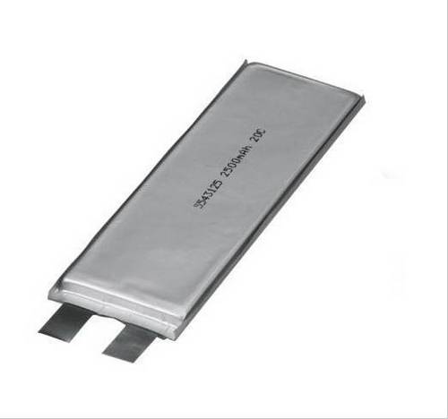
I'm probably going to have to build a belt tensioner, for which I have the design and the idler pulley, but I'm going to wait and see if it's necessary first. Lithium Ion batteries are probably in this bike's future, although the initial tests of the laptop cells are not looking too good. Freewheels on the crank and jackshaft would be nice, because they would allow me to motor without spinning the pedals, and pedal without spinning the motor, respectively, but like I've said about the batteries and many aspects of this project, I think I'm just going to get it working first.

I also recorded a video of me showing how to turn on the bike, and that the motor does in fact spin when I turn the throttle, but it came out shaky and the audio was poor. I'll try again tomorrow.

Monday, February 9, 2015

Batteries!

For a long time now, I've been trying to decide what kind of batteries to use on my bike. I started out with some old 12V, 7.2Ah batteries I pulled from UPSs at my Dad's office. They are heavy, can't supply very much power, and don't store very much charge, but you can't beat free.
I even got a plastic ammo can that fits them perfectly.

At one point, when I thought I had some money to spend, I made a spreadsheet comparing various kinds of batteries in terms of cost, range on my bike, and the most useful metric, $/Wh. You can always take smaller packs and put them together into a large battery pack, so it's not the cost that matters, but how much you're paying per unit of energy. It's also useful for comparing between different types of batteries. You can look at this spreadsheet here, or like almost all the document for this project, it's in the Google Drive folder linked in the sidebar.

Lead acid batteries, as I said above, are pretty poor batteries in almost every way, except that they are incredibly cheap. I won't get into the other kinds of lead acid batteries, but the most common sizes of sealed lead acid batteries are around $0.10/Wh.

Most home-built electric vehicles built now use Prismatic Lithium Ion cells, because they are very large (ranging in size from paperbacks to telephone books) and thus fewer are needed, making them easier to work with. They usually use Lithium Iron Phosphate (LiFePo4) based chemistries, because they are extremely stable and can't catch on fire unlike the other Li-on chemistries. The gold standard right now are the CALB CA cells, which are around $0.40/Wh.
Most commercially built electric vehicles use much smaller, cylindrical cells, such as the 18650, 26650, and 32600 batteries. They can store more energy in a smaller volume than the prismatic cells, the small size provides redundancy in case a few fail, and a number of other advantages in mass production of vehicles, such as easier cooling.The numbers refer to the physical size, for example an 18650, commonly used in laptop batteries and high end flashlights, is 18mm in diameter and 65mm long, which looks like a larger AA battery. The Tesla Model S, for example uses Panasonic NCR18650B cells, which cost $0.49/Wh in medium volumes. Some cylindrical cells, such as the very high quality LiFePo4 18650 cells made by A123, cost upwards of $2/Wh.
The NCR18650Bs I use in my flashlights
For the maximum amount of charge in a given volume and weight, the metal shell must be dropped. The batteries in our phones and many new, ultra-slim laptops are known as Lithium Polymer, or pouch cells, because they literally make the battery into a polymer gel and put it in a plastic pouch, making them lightweight, soft, and fragile. Depending on the chemistry, a sharp impact or puncture to a LiPo battery can easily start a fire. These, however, are the smallest, lightest, and most powerful batteries possible, which is why the remote control industry uses them almost exclusively now. The proliferation of this type of battery in phones, as well ass the explosion of the hobby industry and drones in the last few years, has caused prices to drop quickly. I made a Python program to scrape the Hobbyking website (the only decent place to buy LiPo) and find the cheapest batteries per watt hour, you can see the output spreadsheet over here. Someday I'll get around to to making a website so you can filter the results. I've seen prices as low as $0.32/Wh, including a protective housing, wiring, and connectors. If I went with LiPo batteries, I was going to buy six of these, for only $0.36/Wh.
You may have noticed that I said the cells used in the Tesla are the same as a laptop. And you've probably had an old computer whose battery life just went to zero one day. What you probably didn't know is that most of the cells in that battery were just fine. Most laptop batteries have 6 cells in them (3 in series, 2 in parallel, 3S2P), although a few are 9 (3S3P), or even more rarely, 8 (4S2P). When your battery stops holding a charge, it's really just the weakest of those six cells that won't work. It damages the one it's paired to and the other four are totally fine. And so what people do is open up the batteries, figure out which cells are any good, and then reuse them. This type of battery recycling is surprisingly easy, as long as you don't mind destroying the plastic enclosures that are glued shut around them. There are even factories making good money in China slapping a new label on these used cells and selling them as new (looking at you Ultra/Trust/Sure/UranusFire). You can buy old laptop batteries off of eBay for around $10 a piece, which if you assume you will get an average of 4 working cells at 2Ah a piece, is $0.34/Wh, about the same price as RC LiPo.
However, most people treat these as trash, a hazardous waste to be disposed of (even though they're not toxic, only flammable), instead of as a valuable asset. Of the two local computer stores I visited, one said they already have a contract to give all of their electronics waste to someone, and the other, Computers for Change in Burlington, was happy to give me both dead batteries they had on hand, and said they would bring more from their repair shop. For anyone else thinking of doing this, I should make a guide at some point, but every removable non-Apple laptop battery I've seen has 18650 cells in it. These laptop cells are optimized for energy, not power, by saving space with thinner plates for their electrodes, and so I need a lot of batteries just to get the bike working. I'm going to make a pack that is 10 cells in series, and a minimum of 10 cells in parallel. That's 100 cells or 25 laptop's worth just to get started, with the ultimate goal of around 200 cells. I really should make sure that'll fit in the box. Until I get to that 100 cell number, and have the materials I need to put the pack together, I'm going to keep using the lead acid.
Cracking open a Toshiba laptop battery.
Six Sanyo Cells 
Most of my laptop salvaged batteries
Up next, all the work I've done on the rest of the bike.

Monday, November 3, 2014

Solar Panels on Electric Bikes?

I've seen ideas brought up online about putting solar panels on electric bikes to recharge them, and have always seen them beaten down by the people saying it wasn't practical because you would need so much surface area it wouldn't fit on a bike. However, after seeing pictures of a light electric vehicle with a solar panel built into the roof last week, (if Mark or Griffin could remind me what that was, that'd be great) and being asked the same question today and giving the typical answer with no facts to back it up, I decided to see whether it was feasible.

First, the best case scenario. A bike rack over the rear wheel can hold a solar panel approximately 12" wide by 18" long. The sunniest place in North America is Inyokem California in the high desert, where it is sunny 355 days a year.
They receive 7.7kWh of sunlight energy per square meter on the average day, or about the equivalent of 7.7 hours with the sun directly overhead and no clouds. That means that the solar panel on our bike would receive 1070Wh of sunshine on a normal day in Inyokern. However, solar panels do not convert all of this to electricity. In fact, the most efficient solar panels in a lab are pushing 44% efficiency (awesome graph of this!), but the best commercially available solar panels are the SunPower X-Series which boast 21.5% efficiency. If we assume that our bike panel has the same efficiency, even though SunPower doesn't make any panels this small, that brings our energy down to 230Wh. A typical electric bike traveling at 20 miles/hr, a quick biking pace but somewhat leisurely for an ebike, uses about 17Wh per km, which gives us our average range of 13.8km, or 8.6 miles. This is actually fairly good, considering this is just on electric power, and you can always pedal to extend the range.

However, this is still assuming no losses in the electrical system, using solar panels better than anything on the market, and in the sunniest place in North America. Not all of the power our solar panel generates goes into making the bicycle move. The heat given off by the motor is taken into account in the bicycle efficiency number, but some goes into heat from the rest of the electrical system. Being generous, I would say that the charger has about 96% efficiency, the balancer 99%, the batteries 98%, and the controller 95%, bringing us down to 7.6 miles.
I managed to find a solar panel which is only barely over what I estimated could fit on a bike, and by far the most efficient I could find in this size, rated for 15W. This means that once we account for the wasted sunlight falling on the aluminum frame and the lines on the panel between the solar cells, this solar panel is at 10.6% efficiency, and our range is down to 3.7 miles.
It's not looking good for the solar panel...
The closest city to me right now is Boston, which receives about 3.8 equivalent hours of sun a day, bringing us down even further to 1.9 miles at 20 miles per hour.
Because this person has an electric bicycle, they might want to go a little bit faster, but the problem is that air drag increases with the cube of velocity, so going 30 miles per hour they will have slightly less than half the efficiency as 20 mi/h, so at 30 miles per hour they'd be able to go almost one mile per day in Boston before they need to start pedaling.
And I haven't even gotten to the cloudy days...

As promising as a solar panel looked at the beginning, it soon became apparent why we don't see solar panels on bicycles. They might be useful for people who are off the grid, except for the fact that there is not enough space on bicycles and solar is not reliable enough to count on for getting to work every day. If one has access to the grid, the solar panels on one's bicycle only serve to reduce the already miniscule cost of charging and extend the range of the bicycle, except for the fact that the wind resistance probably costs as much energy as the panel produces. If the aim is to make money by lowering the electrical bill, it makes much more sense to install panels at the house, where they can be the larger, more efficient type as well as perhaps being angled towards the sun, or if one is truly off the grid, an array of solar panels and a battery bank would provide electricity for both the household and transportation.

The one situation where solar panels on electric vehicles do make sense is on vehicles with large, flat roofs which can have panels embedded in them. Not in electric cars, because they use on the order of 20 times more energy than electric bicycles, but on the ultralight, aerodynamic, two person vehicles such as golf carts and the vehicle I saw a solar panel on last week.

Saturday, November 1, 2014

Something to Show

Over the past couple of weeks, I've been slowly doing work on my bike. I installed and learned Autodesk Inventor, which is surprisingly similar to Solidworks, after trying to use AutoCAD and getting incredibly frustrated. A tip for anyone doing CAD work, the online stores Mcmaster-Carr and SDP-SI publish CAD models of most of their parts, so you never have to model a screw or bearing again. Inventor is pretty awesome, I played with the realistic rendering settings and attempted to use the amazing Finite Element Analysis.
This is a view from the front right of the motor unit, the main power switch and motor controller are the things on the front of the box. You can see the back of the motor through the large hole in the side of the box, and on the motor's shaft on the other side is the small pulley. The belt connects that to the large pulley, the big round thing in the back, which turns the shaft and then the sprocket on the side closer to the camera, which goes to the pedals with a chain.

Making the CAD model forced me to think about this more carefully, and I made a few changes, most notably moving the shaft backwards so it hopefully won't hit your leg while pedaling, and changing the belt tensioning system from motor mounting slots to a spring loaded idler. Last week I ordered the last of the electrical components I need to do some tests, just the motor (which still hasn't shipped yet!) and some connectors.

Moving the shaft back allows the controller to go inside the box, against the front wall, which I think would be a better spot. The hole on the side is for putting the motor through when assembling it, because I'm not sure if it make the turn if you put it through the bottom. I was planning on putting a fan over that hole, but I realized that would conflict with the chain going down to the crank, so right now I'm thinking of just covering it with a thin plate. I moved the motor so close to the bottom that I might not even need to drill the hole, I'll see once I get the motor as the dimensions were a little vague.

I'm still not done with the design, I need to figure out the belt tensioner, cooling fan, and rain/splash covers for the top and bottom that still let air through. I have no idea how to design torsion springs for the tensioner so that'll be fun. Now that I have dimensions to what I'm doing I'm going to start drilling holes in the tube this weekend.

MIT Mini Maker Faire

A couple of weeks ago, on October 4th, I traveled down to Boston to compete in a Combat Robotics competition at the MIT Mini Maker Faire. It was hectic and tons of fun, I met some awesome people and didn't have time for any pictures, but somehow won the Antweight Rumble and came home with Best Rookie. After the competition was over I was able to explore the Maker Faire for a few hours. There were tons of 3D printers, tesla coils and robots, but surprisingly the most common thing people brought were electric vehicles. There was a little racetrack set up for the Power Wheels Racing Series as well as more general EV racing. So without further ado, here are all the crazy things MIT students are building, in order of the number of wheels. Sorry for my terrible camera skills.
Flying Nimbus, a segboard
Following the trend of DerpyBike and Herpybike this is known as eNanoHerpyBike 
There were a surprising number of tricycles
Most of these are made at MITERS, aka the MIT Departament of Silly Go Karts
A seriously overpowered and scarily low RC motor tricycle
DriftTrike is somehow even more scary than the last tricycle. That's half an bike with a hub motor on the front.
What makes it scary are those back wheels. They're casters, meaning they can spin around horizontally, so when you go around a corner they turn sideways.
A very narrow tricycle powered by an electric chainsaw. I don't understand how it goes around corners.
Another Tricycle. The whole red front half tilts side to side for cornering
LOLrio Kart. Yes it does use that wheelie bar.
Check out that custom differential!
Yes, this is a wooden go kart
Chibi-Mikuvan, a miniature 1987 Mitsubishi Delica with a giant RC boat motor, angle grinder gearbox and 2010 Ford Fusion Hybrid battery 
There were also a number of practical vehicles. Scooters are a fairly popular way of getting around MIT because the campus is fairly compact and you can bring scooters into class.
So many scooters
Cruscooter, built in the scooter class taught by Charles Guan, the guy who build LOLriokart, eNanoHerpyBike and Chibi-Mikuvan above
In front of the race course with a dubiously practical motorcycle

One of the few electric bicycles. The motor in the center of the photo connects to the wheel on the left side of the bike, without going through the bike's gears, so it's neither mid-drive nor a hub motor
EtekChopper, built by the Daniel Gonzalez, the same guy as Cruscooter
Named after the gigantic brushed motor at it's heart
Another motorcycle conversion, a lot more polished and sporting a more efficient AC motor
The trunk of a 1980s Porsche conversion that I forgot to take a full shot of
And under the hood. Where's the motor?
Last but not least, the 5 wheeled recumbent with a trailer full of batteries that goes several hundred miles 
It's another chain driven non-middrive setup. I don't know why these are so popular, they get the worst of both worlds.
There were a lot of fascinating vehicles at the Maker Faire, and these were not even close to all of them, as I only realized I should be taking photos about halfway through. Even more interesting, however, was talking to all of the people who built these, many of whose blogs I've been following, some of them for years. Jamison Go helped me troubleshoot my robot and after the competition was over, I had a lot of time to kill so I spent a while talking to Shane Colton, Ben Katz, and people from the Cheetah and NASA Rover Challenge teams at MIT.

Next up, progress on my bike.